How the transistor works - 1

Applying voltage with the correct polarity causes current to pass through a
PN junction, and if the polarity of the voltage changes,
no current will pass through the circuit.
If we want to look at the matter simply, the operation of a transistor can be considered as current amplification. Consider a small logic circuit that produces a very small current at its output under certain conditions. You can amplify this current with a transistor, and then use this strong current to turn on and off an electric relay.
There are many cases where you use a transistor to amplify the voltage. It is obvious that this feature is directly inherited from the current amplification feature of this device. It is enough to put the amplified input and output current on a resistor so that the low input voltage is converted to the amplified output voltage. The input current that a
transistor can amplify it, it must have a minimum. If this current is less than the specified minimum, the transistor will not show any current in its output. But as soon as you increase the input current of a transistor to more than the specified minimum, the output current is amplified. You will see. This property of the transistor is usually used to make electronic switches.

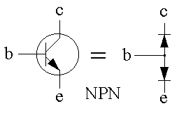
Structurally, a transistor can be modeled with two diodes.
As we mentioned in the previous article ( the first transistors ), the first transistors consist of two semiconductor links and depending on how these links are connected to each other, they can be divided into two main types, PNP or NPN. To understand how a transistor works, we must first know how a semiconductor junction works.
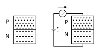
In the first picture you see a PN type semiconductor junction. which is made by connecting two semiconductor pieces P and N to each other. N-type semiconductors have free electrons and P-type semiconductors have a large number of free holes. In simple terms, free hole can be considered as a space where there is a lack of electrons.
If we apply an external voltage to this piece of semiconductor as shown in the figure, a current will be established in the circuit, and if we change the direction of the applied voltage, no current will pass through the circuit (why?).
This semiconductor junction models the simple operation of a diode. As you know, one of the applications of the diode is the rectification of alternating currents. Since a capacitor is usually formed at the junction of the N-type semiconductor and the P-type, the frequency response of a PN junction is completely dependent on the quality of construction and the size of the junction capacitor. For this reason, the first diodes made did not have the ability to work at radio frequencies - for example, for detection.
Usually, in order to reduce this unwanted capacitor, the connection level is reduced and it is reduced to one point. (Continued...)
Related content:
- How does the transistor work? - 5
- How does the transistor work? - 4
- How the transistor works - 3
- How the transistor works - 2
-How the transistor works - 1
April 27, 2005
